Custom thermal components · Australia & New Zealand
Custom Conduction Cooling Plates & Frames
Connect board-mounted heat sources to a defined chassis interface. Custom plates and frames are reviewed against your PCB height map, mechanical stack and enclosure thermal boundary.
Custom component supply. Configuration and acceptance criteria are agreed against your drawing.
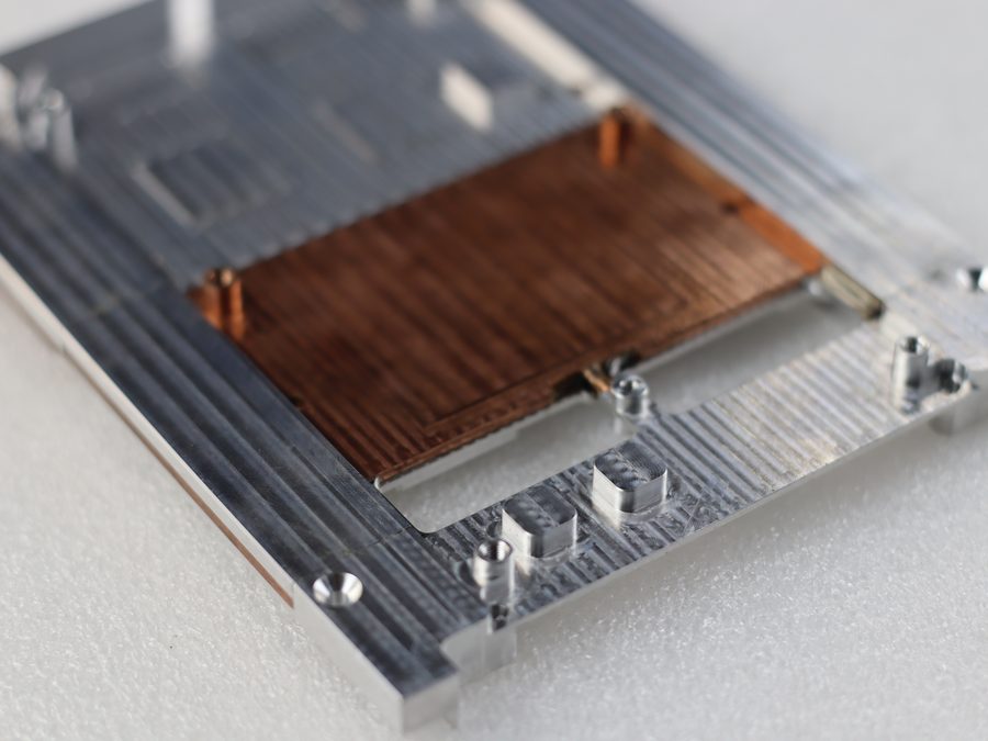
Plate-and-insert construction reference. Material grade, insert joint, surface finish and dimensions require a controlled specification.
When is conduction cooling suitable?
Conduction cooling moves heat through solid interfaces to a chassis or another heat-rejection surface. It is useful when airflow at the PCB is restricted, but the chassis must still reject the heat. Define the temperature at the chassis contact, not only the external ambient.
Specify the complete board-to-chassis path
Interface
Information required
Typical design concern
Component → TIM
Package top height, allowable force, loss and temperature limit.
A pad that is too thick increases resistance; excessive compression can load the package or PCB.
TIM → plate / insert
Local contact height, flatness, material and surface condition.
Tolerance stack can leave some devices under-compressed while overloading others.
Plate → frame / chassis
Contact area, clamp method, mounting sequence and chassis temperature.
Small or poorly clamped contacts can dominate the overall thermal path.
Chassis → surroundings
How the enclosure rejects heat and the expected boundary temperature.
A conductive plate cannot compensate for an enclosure that cannot dissipate the total load.
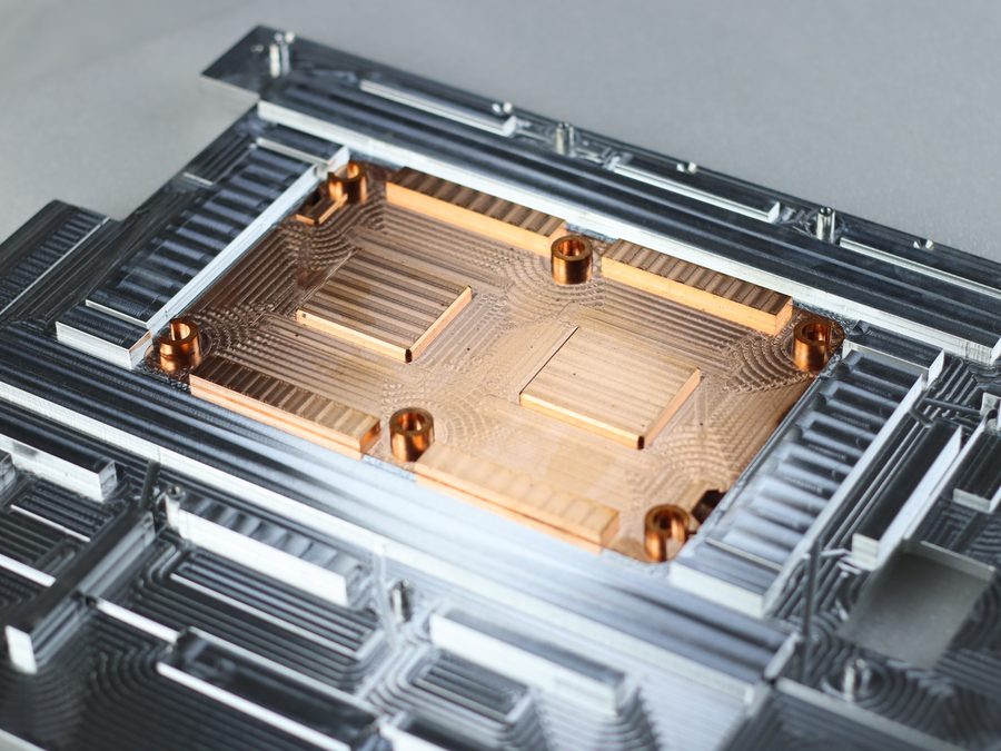
Multi-contact frame reference. Contact locations and heights follow the actual board revision; the image is not proof of compatibility with a standard chassis.
Use inserts where the heat map justifies them
An aluminium structure can provide the main mechanical envelope while local copper spreading elements are evaluated near concentrated sources. Copper also adds mass; a copper insert is not automatically the best solution.
Specify the joining method and inspectable requirements. The joint between materials forms part of the heat path and must be included in the mechanical and thermal assessment.
Resolve height tolerances before freezing the plate
Send nominal, minimum and maximum package heights relative to a common PCB datum. Include board bow, mounting stand-offs, TIM compression range and the plate’s contact-height tolerances. Assess both the hottest device and the device that receives the highest contact force.
For sealed industrial equipment used at Australian or New Zealand sites, define the enclosure temperature during the worst operating duty and its mounting condition. Outdoor exposure, nearby equipment and cabinet ventilation should be reflected in the boundary conditions rather than replaced with a generic room-temperature assumption.
Electrical contact and finish: agree grounding areas, insulated areas and surface-treatment masking. A finish selected for corrosion protection may change electrical or thermal contact behaviour.
What to check on the first assembly
Contact stack
Verify component clearances, contact heights, TIM compression and assembly loads against the released PCB and chassis revisions.
Thermal path
Apply the agreed device loss map and chassis boundary. Record component or case temperatures at specified locations after the agreed stabilisation period.
Environment
Assign vibration, shock, humidity and corrosion requirements to the relevant assembly. Test scope and acceptance limits are project-specific.
Drawings and technical documents
Request a dimensional drawing that identifies the board and chassis datums, contact heights, flatness, insert definition and finish masking. A thermal acceptance record must include the loss map, TIM and chassis contact temperature.
Project-specific documentation
No verified model-specific performance datasheet is available for this custom reference. Request a drawing review and agree the technical document package for your configuration.
Construction reference: ToneCooling European product page. Photographs show reference constructions, not a validated configuration for your project. Numerical performance will only be stated with its source and test conditions.
Drawing-led enquiry
Request a conduction-plate quotation
Define whether the quotation covers a plate, an assembled frame, inserts, fasteners or TIM. This page concerns solid conduction interfaces; any fluid-containing design needs a separate hydraulic and sealing specification.
Opens an editable email checklist; nothing is sent automatically. Attach your drawings before sending. NDA arrangements can be agreed before you share confidential files.
Include these project inputs
PCB outline, revision and component height map
Individual device losses and temperature limits
Chassis contact surfaces and boundary temperature
TIM compression, clamp loads and mounting sequence
Mass limit, finish masking and environmental tests
ToneCooling Australia Pty Ltd coordinates Australian and New Zealand enquiries; manufacturing is in Huizhou, Guangdong, China. Include the destination postcode and required delivery date. Currency, freight, lead time and included inspection documents are confirmed in the quotation.
Engineering questions
Does a 3U or 6U envelope establish VPX compatibility?
No. Provide the applicable interface standard, revision and mechanical details. Envelope size alone does not establish interoperability, thermal performance or qualification.
Can several devices share one plate?
Yes, subject to height, force and thermal-path review. Devices with different heights or temperature limits may require separate contact features or interface thicknesses.
Is pressure testing needed for this plate?
A solid conduction plate has no coolant pressure boundary. Pressure and leak tests apply only if the supplied design contains a fluid circuit; do not substitute these for contact-height and thermal-path checks.