
Liquid → liquid
Server coolant transfers heat to a separate facility-water circuit through the CDU heat exchanger.
Server loop → L2L CDU → Facility water
Compare in-row and in-rack options ↓Compare coolant distribution unit (CDU) configurations and supporting equipment for Australian and New Zealand data centres, GPU deployments and engineering projects.
Start with your heat-rejection path, then match the equipment to your operating temperatures, hydraulic duty and delivery scope.
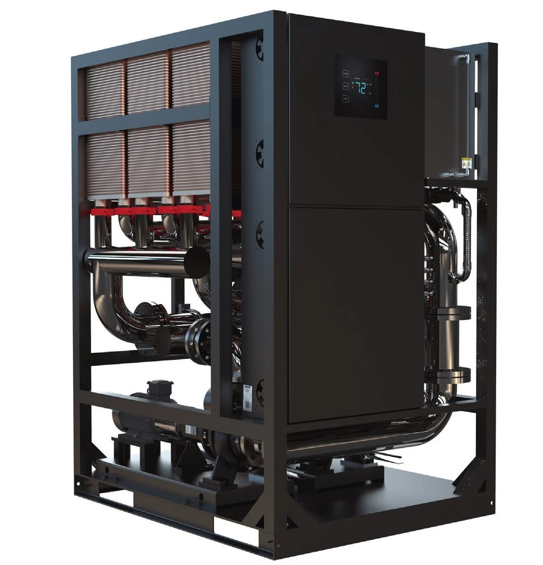
Choose the heat-rejection boundary before comparing catalogue capacities.
Server coolant transfers heat to a separate facility-water circuit through the CDU heat exchanger.
A liquid-to-air CDU rejects heat to the room. Confirm that the room cooling system can remove it.
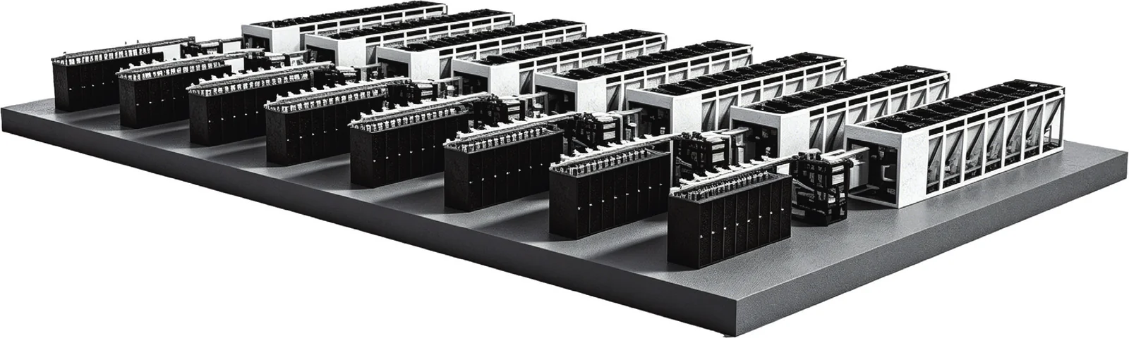
Review dry cooling and pumping as separate duties within the agreed overall system design.
Planning the complete cooling architecture? Visit our data centre liquid cooling solution page ↗
A CDU is only as good as its match to the cold plates downstream. When the CDU, the rack manifold and the cold plates come from different suppliers, each designs to its own assumptions and the gaps show up at commissioning: pumps sized for the wrong pressure drop, supply temperatures that leave no margin at the die, or filtration that does not suit the cold plate’s micro-channels.
Cold plate pressure drop, manifold losses and CDU pump head are calculated on the same model, so the flow each GPU receives is known before anything ships.
Cold plates and CDU loops are pressure-, leak- and flow-tested by the same engineering team, with one set of records.
A single RFQ, a single DFM review and a single set of documents for the liquid side of the rack.
A CDU separates the facility water system from the technology cooling system that runs through the servers. Facility water passes through one side of a plate heat exchanger; a clean, conditioned coolant (typically PG25) circulates on the other side, through the rack manifold and into the cold plates. The CDU’s pumps, filters and controls hold flow, pressure and supply temperature within the limits the IT equipment needs, and its sensors watch for leaks and coolant quality.
Compare equipment arrangements, review model-specific selection inputs and download the relevant datasheets for your Australian or New Zealand project.
Four CDU configurations, plus dry cooling and pumping equipment. Images show each product family, not every model or optional configuration.
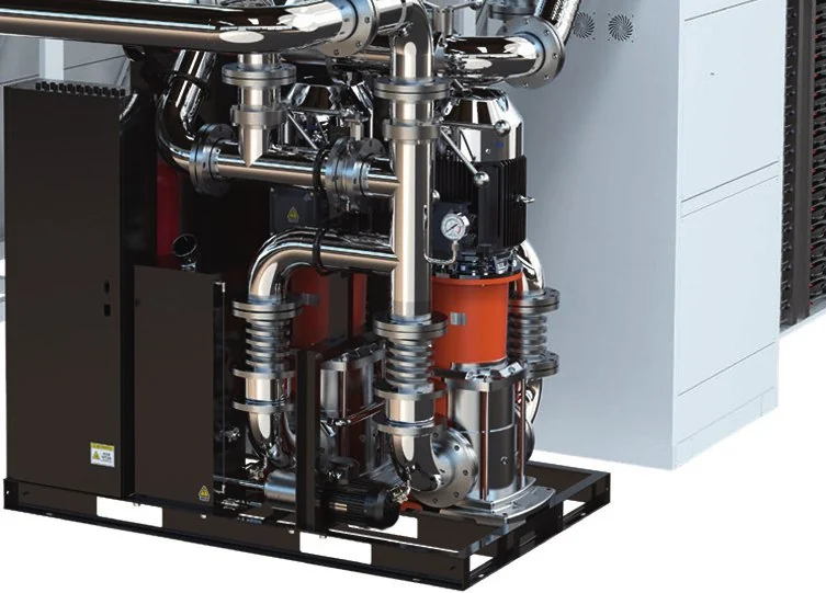
Move coolant through the specified circuit. A pump skid is not, by itself, a heat-rejection device.
Free 1-page PDF · No form required
Inside: dimensions, flow, power supply and control interfaces.
TC-IPS-2000Download Datasheet (PDF) ↓TC-IPS-1600Download Datasheet (PDF) ↓TC-IPS-1000Download Datasheet (PDF) ↓TC-IPS-600Download Datasheet (PDF) ↓Need help selecting? Ask our team ↗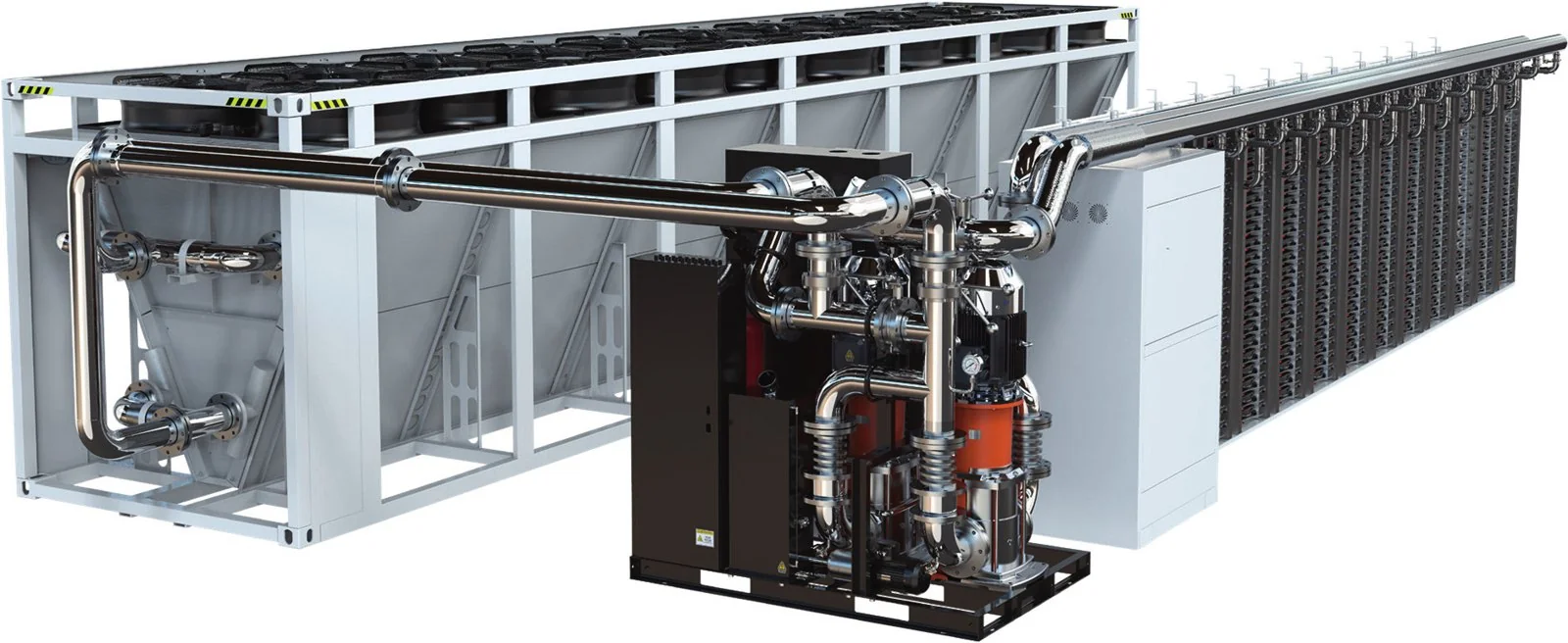
Reject loop heat to outdoor air. Check performance at the actual site design ambient.
Free 1-page PDF · No form required
Inside: dimensions, flow, power supply and control interfaces.
TC-DCU-2000Download Datasheet (PDF) ↓TC-DCU-1600Download Datasheet (PDF) ↓TC-DCU-1000Download Datasheet (PDF) ↓TC-DCU-600Download Datasheet (PDF) ↓TC-DCU-300Download Datasheet (PDF) ↓Need help selecting? Ask our team ↗Transfer heat between the server coolant loop and a facility-water loop.
Free 1-page PDF · No form required
Inside: dimensions, flow, power supply and control interfaces.
TC-CDU-L2000CDownload Datasheet (PDF) ↓TC-CDU-L1600CDownload Datasheet (PDF) ↓TC-CDU-L1000CDownload Datasheet (PDF) ↓TC-CDU-L600CDownload Datasheet (PDF) ↓TC-CDU-L300CDownload Datasheet (PDF) ↓Need help selecting? Ask our team ↗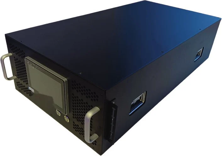
Provide liquid-to-liquid heat exchange within the rack envelope.
Free 1-page PDF · No form required
Inside: dimensions, flow, power supply and control interfaces.
TC-CDU-L250RDownload Datasheet (PDF) ↓TC-CDU-L200RDownload Datasheet (PDF) ↓TC-CDU-L150RDownload Datasheet (PDF) ↓TC-CDU-L120RDownload Datasheet (PDF) ↓TC-CDU-L100RDownload Datasheet (PDF) ↓TC-CDU-L50RDownload Datasheet (PDF) ↓TC-CDU-L35RDownload Datasheet (PDF) ↓Need help selecting? Ask our team ↗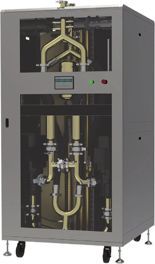
Transfer server-loop heat into the surrounding air. Room cooling must carry this load.
Free 1-page PDF · No form required
Inside: dimensions, flow, power supply and control interfaces.
TC-CDU-A600CDownload Datasheet (PDF) ↓TC-CDU-A300CDownload Datasheet (PDF) ↓TC-CDU-A120CDownload Datasheet (PDF) ↓TC-CDU-A60CDownload Datasheet (PDF) ↓Need help selecting? Ask our team ↗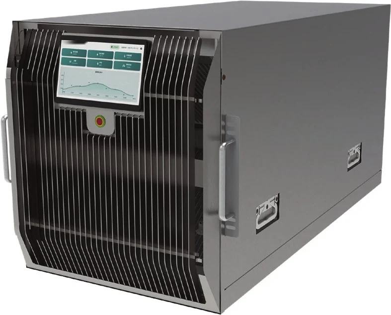
Bring a local coolant loop to a rack while rejecting heat to room air.
Free 1-page PDF · No form required
Inside: dimensions, flow, power supply and control interfaces.
TC-CDU-A30RDownload Datasheet (PDF) ↓TC-CDU-A24RDownload Datasheet (PDF) ↓TC-CDU-A15RDownload Datasheet (PDF) ↓TC-CDU-A6RDownload Datasheet (PDF) ↓Need help selecting? Ask our team ↗Direct English catalogue downloads, with no form to complete. Each link identifies a specific model; a family image does not establish that model’s dimensions or configuration.
Catalogue references are for initial selection. Request the current controlled revision, duty-point performance, pump curve and electrical details for the equipment being quoted.
A delivery address alone does not define operating conditions. Include the following in your project brief.
State the city and postcode, indoor or outdoor location, design ambient and coolant supply/return temperatures. For exposed installations, identify coastal exposure, dust and any freezing conditions.
Provide coolant chemistry, glycol concentration if used, required flow, allowable pressure drop and wetted-material restrictions. Specify the available facility-water temperatures and pressure.
Confirm site voltage, phase, frequency, electrical connection, alarm interface and monitoring protocol. Identify the documents your electrical contractor and project reviewer require.
Share rack or plant-room dimensions, connection standards, service clearances, lifting access and noise constraints. Identify who will install, fill, flush and commission the equipment.
Short answer: choose an in-rack coolant distribution unit when one rack, or a few, needs liquid cooling and facility water can reach each rack. Choose an in-row CDU when a row of GPU or HPC racks shares one secondary loop and you want the pumps, filtration and controls outside the IT racks. In our reference range, in-rack liquid-to-liquid units run from 35 kW to 250 kW in 4U to 6U, and in-row liquid-to-liquid units run from 300 kW to 2,000 kW as floor-standing cabinets.
| Selection factor | In-rack liquid-to-liquid CDU | In-row liquid-to-liquid CDU |
|---|---|---|
| Catalogue capacity (reference range) | 35–250 kW | 300–2,000 kW |
| Form factor | 4U to 6U, 482 mm wide, mounts in the IT rack | Floor-standing cabinet in the row, from 600 × 1200 × 2000 mm |
| Flow reference | 120–400 L/min | 500–3,200 L/min |
| Pump arrangement | 1+1 | 1+1 |
| Catalogue electrical supply | AC 220 V (35 kW model) to 3-phase 380 V or 480 V (250 kW model) | 3-phase 380 V 50/60 Hz or 480 V 60 Hz |
| Best suited to | Pilot racks, single high-density GPU racks, colocation cages | Rows of GPU or HPC racks on a shared secondary loop |
| Main trade-off | Uses rack units that could hold IT; one CDU per rack | Needs floor space in the row and secondary pipework to every rack |
Catalogue references from the TC-CDU-L35R, TC-CDU-L250R, TC-CDU-L300C and TC-CDU-L2000C model pages (35 °C / 45 °C facility water reference, 5 K approach). Duty-point performance is confirmed at quotation.
An in-rack CDU suits rack-level liquid cooling where each rack is its own project: a pilot GPU rack, a single high-density rack in an air-cooled hall, or a colocation cage where you cannot run a shared secondary loop. The coolant loop stays inside the rack, so the hydraulic budget is short and easy to test before shipment. The cost is rack space and one CDU per rack.
An in-row CDU suits a row or pod of GPU racks that will be built out together. One unit (or an N+1 pair) feeds several racks through a secondary header, keeping pumps and filters out of the IT racks and giving service access from the aisle. Plan floor space, secondary pipework to each rack and the facility-water connection early.
Use a liquid-to-air CDU. It moves heat from the cold plate loop into the room air, so the room cooling must be able to carry that load. Our liquid-to-air reference designs start at 6 kW in-rack and go to 600 kW in-row.
The cold plates fix the flow and pressure the CDU must deliver. Our GB300 4G+2C cold plate kit was tested at 1.7 L/min and 12.06 kPa per GPU cold plate, and the GB200 cold plate kit is specified at 2.5 L/min and 35 ± 5 kPa. Multiply by the module count per rack, add manifold losses, and you have the flow and head the CDU must provide with margin. Because we make the cold plates, manifolds and CDU, that calculation is done on one hydraulic budget. Projects in New Zealand follow the same method; see liquid cooling for New Zealand data centres.
Next step: send the rack count, heat load per rack and the heat-rejection path. An engineer reviews every RFQ and replies by email with next steps. Request a CDU quotation →
Start from the heat to be removed and the temperature rise the cold plates can accept. The coolant flow follows from:
Q = P ÷ (ρ · cp · ΔT)
For a 120 kW rack on PG25 (density about 1,025 kg/m³, specific heat about 3.9 kJ/kg·K) with a 10 °C rise, the required flow is roughly 3.0 L/s, or about 180 L/min. The CDU is then selected with head to spare for the manifold and cold plate pressure drop at that flow, and with an approach temperature that keeps the supply inside the IT equipment’s inlet window.
We run this calculation, and the cold plate CFD behind it, as part of every quotation.
Sites in Western Australia, Queensland and inland New South Wales see summer peaks above 45 °C. Warm-water designs aligned to the ASHRAE TC 9.9 liquid cooling classes let dry coolers reject heat for more of the year and reduce chiller hours.
Closed-loop liquid cooling recirculates coolant instead of evaporating it. Pairing CDUs with dry coolers removes cooling tower water use on the heat rejection side.
Many Australian facilities were built for air. Liquid-to-air CDUs let individual high-density racks move to direct-to-chip cooling without new facility pipework.
CDUs are electrical equipment. Because every unit is built to project specification, the electrical safety pathway is defined per project at quotation: the applicable standards, the documentation set, and the registration steps under the Electrical Equipment Safety System (EESS) where the equipment is in scope. We confirm this in writing before an order is placed, so there are no surprises at site acceptance.
Agree the model, configuration, included pumps and fittings, coolant scope, drawings, acceptance criteria and inspection records.
Provide the destination and receiving requirements. Confirm currency, delivery terms, freight, import responsibilities and lead time in the quotation.
Installation, commissioning, spare parts, warranty and service arrangements must be expressly agreed. Local stock and on-site response are not assumed.
Share your project brief for equipment selection and a configuration-specific quotation.
Email your CDU enquiry ↗No. Selection must be checked at your operating temperatures, flow rates, coolant properties and available heat-rejection conditions.
A liquid-to-air CDU transfers the server heat into the room air. The room cooling system still needs sufficient capacity to reject that heat.
Yes. Provide the operating conditions and delivery details for each site, with separate installation and commissioning responsibilities where required.
No. The range includes four CDU configurations and two supporting equipment families: integrated pump skids and integrated dry cooling units.
No. Every CDU is engineered to the project. The reference platforms shorten design time, but capacity, connections, controls and electrical supply are specified for each installation.
Yes. Supplying both is the main reason customers choose us: one hydraulic budget, one test programme and one set of documents for the liquid-cooled rack.
Reference designs run from 6 kW in-rack liquid-to-air units to 2,000 kW in-row liquid-to-liquid units, with integrated dry coolers and pump skids for heat rejection up to 2,000 kW.
PG25 is the typical technology-loop coolant. Other glycol mixes can be specified to suit the cold plates and the site’s frost and corrosion requirements.
The electrical safety pathway is agreed per project at quotation, including any EESS registration where the equipment is in scope. We do not claim certification before it is confirmed for the specific unit.
Choose an in-rack CDU for one or a few racks where facility water reaches each rack; our reference range is 35–250 kW in 4U to 6U. Choose an in-row CDU when a row of racks shares one secondary loop; our reference range is 300–2,000 kW. The final choice is confirmed against your heat load, flow, pressure budget and floor space.
Rack-level liquid cooling puts the coolant distribution unit inside, or right beside, the rack it serves. The CDU separates the cold plate loop from facility water or room air and controls flow, pressure and supply temperature for that rack. It is the usual starting point for a first GPU rack before a row-level system is built.
More data centre liquid cooling equipment
CDUs work with the rest of the loop. Related equipment supplied by ToneCooling Australia:
AI cold plate kits · datasheets
In-rack liquid-to-liquid · all models
In-row liquid-to-liquid · all models
In-rack liquid-to-air · all models
In-row liquid-to-air · all models
Dry coolers · all models
Pump skids · all models