
Mechanical repeatability
Agree the force measurement, contact-height checks and package tolerances. Inspect the assembly after repeated loading for marks, interference and loss of alignment.
Specify the cooled contact head around your package, socket and test sequence. This page is for drawing-led thermal components supplied to AU/NZ test-equipment developers and laboratories, with force, temperature measurement and repeated contact defined together.
Custom component supply. Configuration and acceptance criteria are agreed against your drawing.
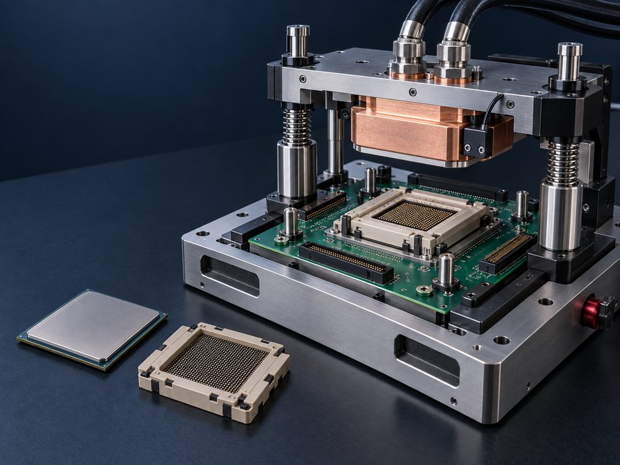
The package contact geometry, allowed force, thermal load sequence and measurement location. Coolant temperature, head-surface temperature and device junction temperature are different variables. Define which one is controlled and how acceptance will be measured.
| Interface | Drawing inputs | Review focus |
|---|---|---|
| Lidded package | Lid dimensions, flatness, allowable force and neighbouring keep-outs. | Contact coverage, spreading resistance and repeatability of the interface layer. |
| Bare die | Die outline, height limits, surrounding features and permitted loading. | Protection against edge contact, uneven load and interference. A lid-contact drawing cannot simply be reused. |
| Repeated insertion | Package variation, travel, fixture guidance and load application method. | Contact consistency after unloading, cleaning and reloading. |
| Interface material | Thickness, compression, residue limits and replacement sequence. | Thermal resistance, cleanliness and carry-over between devices. |
A short burst and a continuous load can have the same peak power but require different test responses. Supply the power-versus-time sequence, dwell periods, starting condition and permitted overshoot or settling behaviour. Identify whether a heater, TEC or other actuator is included in the fixture.
Measurement concept only; not a cross-section of the illustrated fixture.
A temperature measured in the head does not directly establish die temperature. Record sensor mounting, acquisition rate and how the measured value relates to the required acceptance variable. Any thermal model used for that relationship needs its assumptions and validation stated.
For AU/NZ prototype laboratories, state the available chiller, ambient humidity and fluid connections, together with the destination site and intended service support. If a surface can fall below the local dew point, the test-system designer must define moisture control and interlocks before operation.
Repeated loading changes the practical requirements: provide the head travel, cable and hose movement, cleaning method and intended contact-cycle count. Define whether the thermal interface is reusable, replaced for each device, or restricted because of residue. No residue-free behaviour or lifetime is assumed without the relevant evaluation.
Agree the force measurement, contact-height checks and package tolerances. Inspect the assembly after repeated loading for marks, interference and loss of alignment.
Repeat the same power profile with controlled starting conditions. State the number of repeats and acceptable variation in the chosen temperature variable.
Agree operating pressure, leak-test method, connections and moving-hose limits. Include the position of coolant ports relative to the socket and sensitive electronics.
Request the contact-head drawing, datum scheme, contact-surface requirements and sensor provisions. Link the test plan to the package revision and fixture state. A component drawing or pressure report is not a complete tester qualification.
No verified model-specific performance PDF is available for this reference. The button requests a drawing and specification review; it is not a datasheet download.
Request drawings and specificationConstruction reference: ToneCooling catalogue page. Reference images do not establish performance or qualification. The accepted drawing revision and agreed test conditions define the supplied component.
Identify the cold head, mounting parts, sensors, heater or TEC requested. Chillers, controllers, safety interlocks, sockets and complete test automation are outside the component scope unless expressly included. NDA arrangements can precede confidential drawing transfer.
Prepare my enquiry by emailOpens an editable email checklist; nothing is sent automatically. Attach your drawings before sending. NDA arrangements can be agreed before you share confidential files.
ToneCooling Australia Pty Ltd coordinates Australian and New Zealand enquiries; manufacturing is in Huizhou, Guangdong, China. Include the destination postcode and required delivery date. Currency, freight, lead time and included inspection documents are confirmed in the quotation.
No. The temperature rise also depends on the device, interface, head construction, flow and load history. Agree the measurement or validated model connecting coolant conditions to the device limit.
Only after reviewing the tolerance range, travel and load distribution. A compliant fixture or interchangeable contact may be needed; this must be defined rather than assumed.
No. A packaged-device contact head and a wafer chuck have different mechanical, thermal and handling interfaces. This page does not offer a complete wafer probing or temperature-control system.