
Hydraulic duty
Name both pressure taps and document flow-meter location, fluid temperature, valve states and instrument accuracy. Agree tolerances before testing.
Build a pressure budget that a pump, cold-plate and hose supplier can all use. This guide focuses on the circuit calculation and acceptance boundary for AU/NZ equipment integrators, rather than offering a universal flow-per-kilowatt rule.
Project preparation guidance. Examples are illustrative, not ToneCooling product ratings.
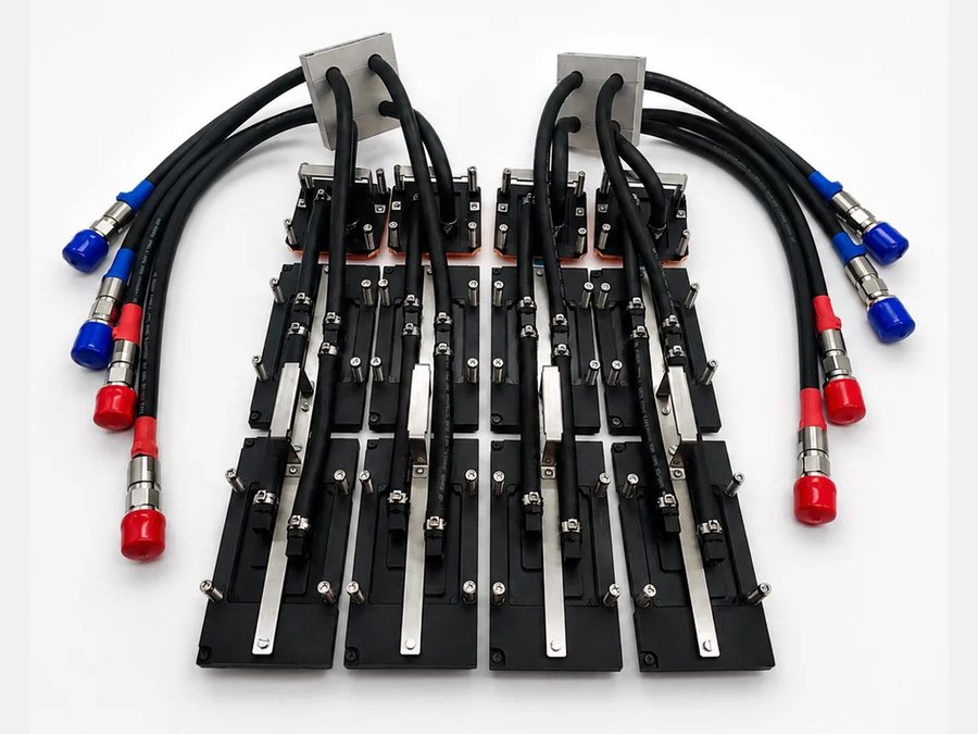
Specify the loss between named supply and return measurement points at the required flow, fluid and temperature. Add losses in series along each flow path. For parallel branches, calculate each branch at its own flow and solve the flow distribution; do not add all branch pressure drops as if they were in series.
| Circuit item | Required input | How it enters the budget |
|---|---|---|
| Cold plates | Part / revision and pressure-drop curve for the specified fluid. | Use each device’s branch flow, not automatically the pump total. |
| Hoses and fittings | Internal diameter, length, bends and exact connector pair. | Include both supply and return paths and installed restrictions. |
| Common equipment | Heat exchanger, filter, valves and shared headers inside the boundary. | Common sections carry combined flow where applicable. |
| Pump or CDU outlet | Available differential-pressure curve and control mode at the handover points. | Do not count internal CDU losses twice if net external pressure is already stated. |
| Operating cases | Normal duty, permitted partial population and agreed fault / maintenance cases. | Review changed branch flows and clean versus service filter conditions. |
Assume two identical parallel branches, each needing 2 L/min. At that branch flow, one branch has 18 kPa across its cold plate, 7 kPa across its mated connector sets and 5 kPa across its hoses: 30 kPa per branch. Total flow is 4 L/min.
If the branches differ, their flows will not necessarily split evenly. Include header losses, balancing elements and valve states, then compare the resulting system curve with available pump pressure. The operating point depends on the pump curve or control mode; a maximum-flow label and a maximum-head label are not one simultaneous operating point.
For a simple single-phase heat balance, Qheat = mass flow × specific heat × coolant temperature rise. Use density and specific heat for the selected fluid and temperature to convert volume flow. This estimates coolant warming, not the device junction temperature or the pressure drop.
An indoor AU/NZ laboratory and an outdoor equipment cabinet can require different fluid temperatures and freeze-protection assumptions. State the fluid manufacturer, mixture basis and concentration. Temperature-dependent viscosity can change losses; a warm-water curve does not establish cold-start performance with glycol.
Include the delivery site, commissioning owner, flush/fill procedure and accessible measurement ports in the handover package. Static fill pressure, component working pressure and pump differential pressure are separate values. Closed-loop circulation is not normally sized by adding the full building height as a continuous lift; elevation still affects local static pressure, filling and venting.
Name both pressure taps and document flow-meter location, fluid temperature, valve states and instrument accuracy. Agree tolerances before testing.
Confirm the limiting branch reaches its required flow. A correct total loop flow alone does not prove every device is adequately supplied.
State filter service threshold, isolation sequence and restart/venting checks. Allocate any pressure allowance instead of applying an unexplained percentage.
These references support the selection method. They do not validate a ToneCooling configuration or establish interchangeability.
Review the supplied BOM and factory-to-site assembly boundary.
Obtain equipment data for the required external duty and operating conditions.
Source review: 21 September 2026. Use the selected component’s current controlled datasheet and drawing for procurement.
Define whether the quotation covers individual parts, an assembled loop or additional equipment. Pump selection, site filling and commissioning are included only when listed in the agreed scope.
Prepare my enquiry by emailOpens an editable email checklist; nothing is sent automatically. Attach your drawings before sending. NDA arrangements can be agreed before you share confidential files.
ToneCooling Australia Pty Ltd coordinates Australian and New Zealand enquiries; manufacturing is in Huizhou, Guangdong, China. Include the destination postcode and required delivery date. Currency, freight, lead time and included inspection documents are confirmed in the quotation.
Only components on the same series path can be summed at the appropriate flow. Parallel paths require a network calculation; shared equipment uses the combined flow.
It can reduce pumping demand, but thermal performance, flow distribution, size and cleanliness still matter. Compare designs at a common duty and fluid boundary.
No. Pressure drop measures hydraulic resistance during flow. Leak and proof tests have different purposes, pressures and acceptance criteria.
Related liquid loop pages